Under normal circumstances Vertical Turbine Pumps have a thrust load acting parallel to the pump shaft. This load is due to unbalanced pressure, dead weight and liquid direction change. Optimum selection of the motor bearing and correct determination of required bowl lateral for deep setting pumps require accurate knowledge of both the magnitude and direction (usually down) of the resultant of these forces. In addition, but with a less significant role, thrust influences shaft H.P. rating and shaft critical speeds. IMPELLER THRUST
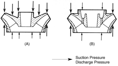
Impeller Thrust in the downward direction is due to the unbalanced discharge pressure across the eye area of the impeller. See diagram A.

To accurately determine impeller thrust, thrust-capacity curves based on actual tests are required. Such curves now exist for the "A" Line. To determine thrust, the thrust factor "K" is read from the thrust-capacity curve at the required capacity and given RPM. "K" is then multiplied by the Total Pump Head (Final Lab Head) times Specific Gravity of the pumped liquid. If impeller thrust is excessively high, the impeller can usually be hydraulically balanced. This reduces the value of "K". Balancing is achieved by reducing the discharge pressure above the impeller eye by use of balancing holes and rings. See diagram B.
NOTE:
Although hydraulic balancing reduces impeller thrust, it also decreases efficiency by 1 to 5 points by providing an addi-tional path for liquid recirculation.
NOTE:
Although hydraulic balancing reduces impeller thrust, it also decreas-es efficiency by one to five points by providing an additional path for liquid recirculation. Of even greater concern is that should the hydraulic balancing holes become clogged, (unclean fluids, fluids with solid content, intermittent services, etc.), the impeller thrust will increase and possibly cause the driver to fail. Hydraulically balanced impellers cannot be used in applications requiring rubber bowl bear-ings because the flutes on the inside diameter of the bearings pro-vide an additional path to the top side of the impeller, thus creating an additional down thrust.
Hydraulically balanced impellers should be used as a "last resort" for those situations where the pump thrust exceeds the motor thrust bearing capabilities.


