Specifically not recommended is a pipe directly connected to a sump with suction intakes dose to the sump inlet, since this results in an abrupt change in the flow direction. Centering pumps or suction pipes in the sump leaves large vortex areas behind the Intake which will cause operational trouble.
If the sump velocity, as shown in Fig. 10 (D), can be kept low (approximately 1.5 feet per second), an abrupt change from inlet pipe to sump can be accommodated if the sump length equals or exceeds the values shown. As ratio Z/P increases, the inlet velocity at P may be increased up to an allowed maximum of eight feet per second at Z/P 10. Intakes "in line" are not recommended unless the ratio of sump to intake size is quite large and intakes are separated by a substantial margin longitudinally. A sump can generally be constructed at less cost by using a recommended design.
As shown in Fig. 10 (E), it is sometimes desirable to Install pumps in tunnels or pipe lines. A drop pipe or false well to house the unit with a vaned inlet elbow facing upstream is satisfactory in flows up to eight feet per second. Without Inlet elbow, the suction bell should be positioned at least two pipe (vertical) diarneters above the top of the tunnel. The unit should not be suspended in the tunnel flow, unless the tunnel velocity is less than two feet per second. There must be no air along the top of the tunnel, and the minimum submergence must be provided.
In general: Keep inlet velocity to the sump below two feet per second. Keep velocity in sump below 1.5 feet per second. Avoid changing direction of flow from inlet to pump or suction pipe, or change direction gradually and smoothly, guiding flow.
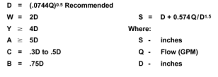
Fig. 7 Sump Dimensions
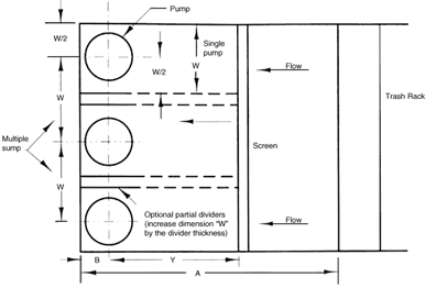
Fig. 8 Sump dimensions, Plain view, wet pit type pumps
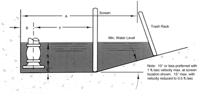
Fig. 9 Sump dimensions, elevation view, wet pit type pumps
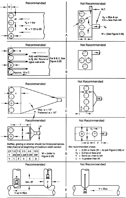
Fig. 10 Mulitple pump installations
