
Friction Loss of Pulp Suspensions in Pipe
I. INTRODUCTION
In any stock piping system, the pump provides flow and develops hydraulic pressure (head) to overcome the differential in head between two points. This total head differential consists of pressure head, static head, velocity head and total friction head produced by friction between the pulp suspension and the pipe, bends, and fittings. The total friction head is the most difficult to determine because of the complex, nonlinear nature of the friction loss curve. This curve can be affected by many factors.
The following analytical method for determining pipe friction loss is based on the recently published TAPPI Technical Information Sheet (TIS) 408-4 (Reference 1), and is applicable to stock consistencies (oven-dried) from 2 to 6 percent. Normally, stock consistencies of less than 2% (oven-dried) are considered to have the same friction loss characteristic as water.
The friction loss of pulp suspensions in pipe, as presented here, is intended to supersede the various methods previously issued.
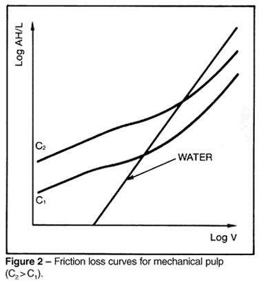
II. BACKGROUND II. BACKGROUND Figure 1 and Figure 2 show typical friction loss curves for two different consistencies (C 2 > C 1) of chemical pulp and mechanical pulp, respectively.
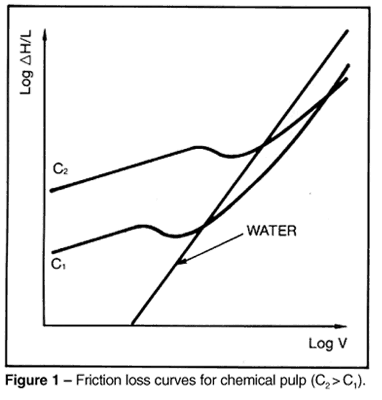
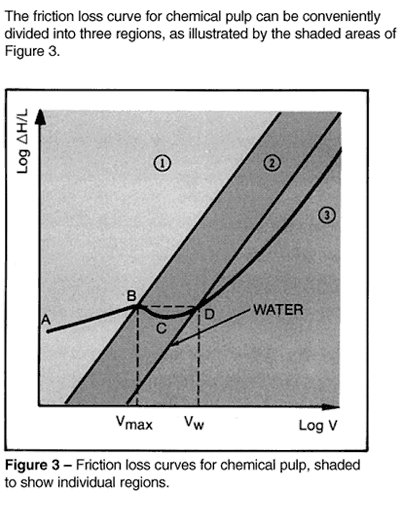
These regions may be described as follows:
Region 1 (Curve AB) is a linear region where friction loss for a given pulp is a function of consistency, velocity, and pipe diameter. The velocity at the upper limit of this linear region (Point B) is designated V max .
Region 2 (Curve BCD) shows an initial decrease in friction loss (to Point C) after which the friction loss again increases. The intersection of the pulp friction loss curve and the water friction loss curve (Point D) is termed the onset of drag reduction. The velocity at this point is designated V w .
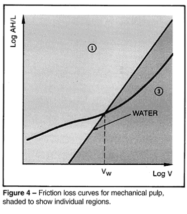
Region 3 (Curve DE) shows the friction loss curve for pulp fiber suspensions below the water curve. This is due to a phenomenon called drag reduction. Reference 2 describes the mechanisms which occur in this region.
Regions 2 and 3 are separated by the friction loss curve for water, which is a straight line with a slope approximately equal to 2.